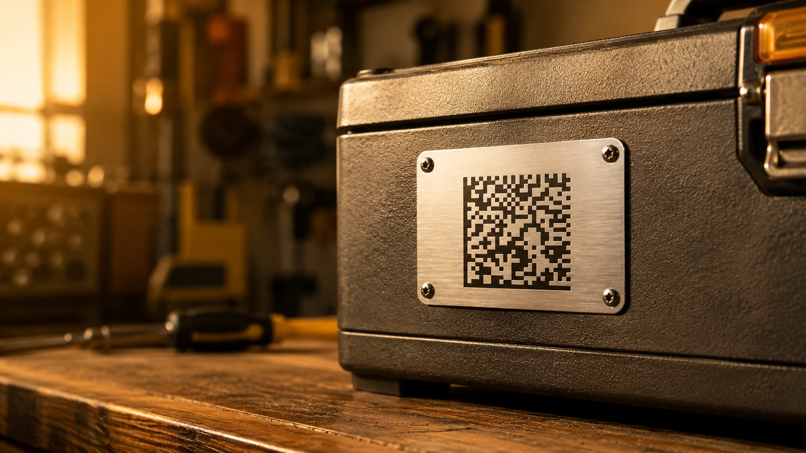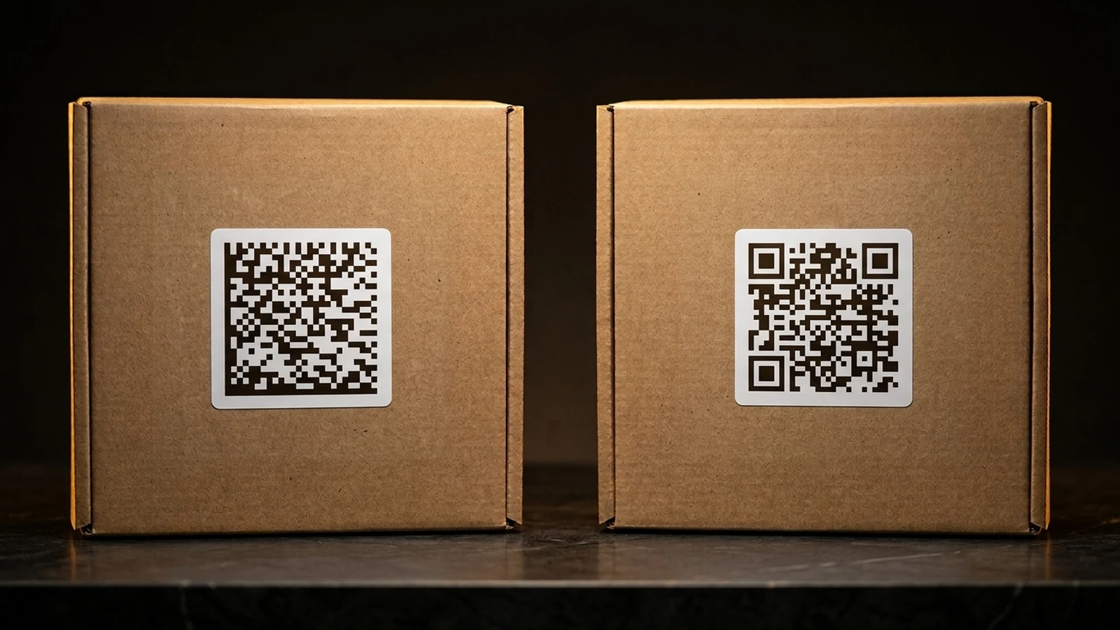
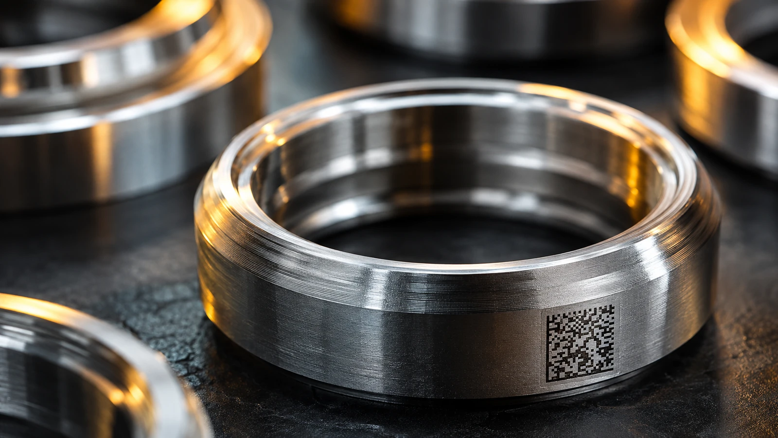
When a code needs to survive on a part for the part's entire working life, printing it on a label is often not an option. Direct part marking, usually abbreviated DPM, means placing a Data Matrix code permanently onto the surface of the physical item, such as metal, plastic, glass, or a printed circuit board, rather than printing it on paper or film and applying it as an adhesive label. The mark becomes part of the object. It cannot be peeled off by accident, dissolved by a solvent, scraped away during handling, or lost when a label's adhesive eventually fails after years of vibration, heat, or humidity.
That permanence is the entire point. A jet engine bracket, a surgical retractor, a transmission housing, or a semiconductor package may need to be individually identifiable for the full duration of its service life, which in aerospace and defense contexts can run for decades and pass through several owners. A label glued to a part that later gets repainted, autoclaved, machined, or degreased with solvent will rarely survive that history intact. Direct part marking exists to solve a problem labels cannot: keeping a permanent, machine-readable identity attached to a part no matter what happens to it physically. That is why it shows up so consistently in aerospace, defense, automotive, electronics, and medical device manufacturing, all industries where a part's history needs to be traceable years after it left the factory floor.
What Makes Direct Part Marking Different From a Printed Label?
A printed label is a separate object attached to a part after the fact. A direct part mark is not attached to anything; it is a physical change to the part's own surface, made by removing material, using a laser's heat to change the surface color without removing material, striking a pattern of dimples into the metal, depositing cured ink, or applying a chemical that reacts with the surface until it discolors or etches. However it is done, the code and the part are now the same physical object, which is a fundamentally different relationship than gluing a sticker onto something.
Labels also simply are not practical in a lot of real manufacturing scenarios. A part can be too small to carry a label with a usable quiet zone around the code. It can have a curved, textured, or machined surface that a flat adhesive label will not sit flush against. It might be painted, plated, heat-treated, or sterilized after marking, any of which can destroy a label but leaves a properly executed direct mark untouched. Medical instruments that go through hundreds of autoclave cycles over their service life are a good example: a label would fail long before the instrument's usable life ends, but a laser mark on the same surface can outlast the instrument itself.
The other reason DPM matters is what it enables downstream. A part carrying a permanent, unique identifier can be tied back to its manufacturing lot, the operator or machine that produced it, its inspection records, and every maintenance event it goes through afterward. That is different from a class-level code that just says "this is part number X"; a serialized direct mark says "this is the specific unit of part number X that was produced on this date, from this material lot, and inspected by this record." For maintenance, repair, and overhaul operations, for recall investigations, and for counterfeit detection in supply chains where genuine and counterfeit parts can otherwise look identical, that unit-level identity is the whole reason the mark exists.
Which Marking Method Should You Choose: Laser, Dot Peen, Inkjet, or Chemical Etch?
There is no single best way to mark a part. The right method depends on the substrate, how durable the mark needs to be, how many parts you are marking per hour, how much surface preparation is realistic on a production line, and whether the marking process itself is allowed to touch or heat the part at all. The four methods below cover the large majority of real industrial marking, and each one trades off durability, speed, cost, and material compatibility differently.
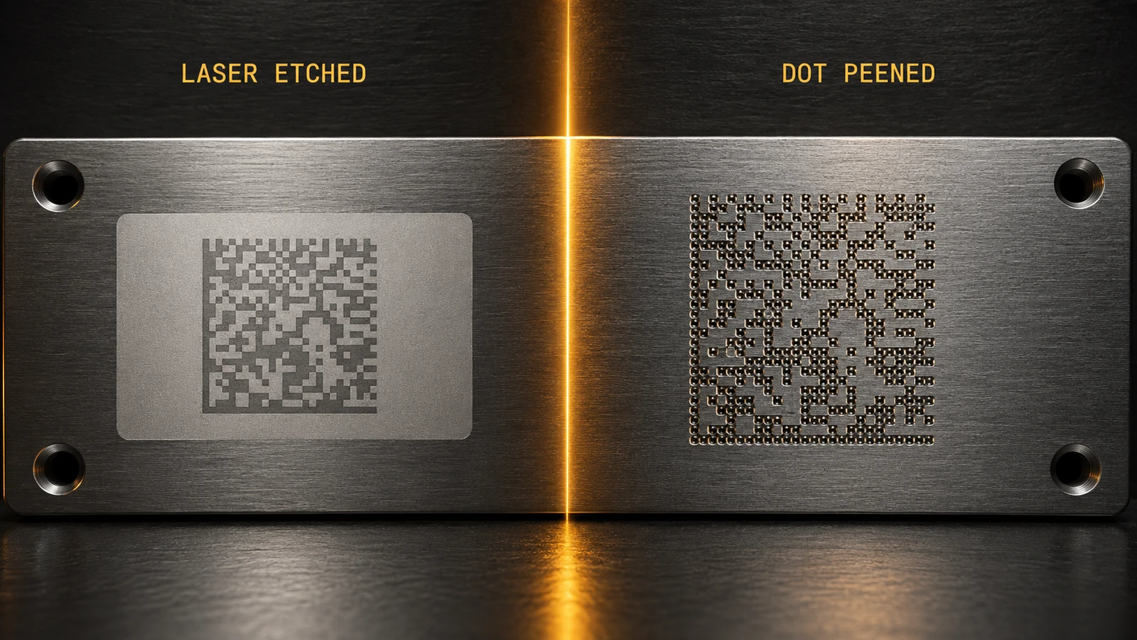
Laser marking is really two distinct processes that get lumped under one name. Laser annealing changes the color of a metal's surface by controlled heating, without removing any material or cutting into it. It is common on stainless steel and titanium, particularly in medical device work, because it leaves the surface geometry unchanged: no grooves or pits form that could trap bacteria or residue between sterilization cycles, which matters enormously for reusable surgical instruments. Laser engraving, or ablation, is the other laser process, and it does remove material, cutting a shallow physical groove into the surface to form each module. It works across a wider range of materials than annealing and produces a mark you can feel with a fingernail, but it is more aggressive toward the part and not appropriate for delicate or thin-walled components. It is worth being precise about terminology here: laser marking, the act of physically creating a code on a surface with a laser, has nothing to do with laser scanning, an older barcode-reading technology built around a sweeping laser line that reads linear barcodes and, at most, stacked codes such as PDF417, but not matrix codes. A laser can be used to make a Data Matrix code; a laser scanner cannot read one.
Dot peening uses a mechanical stylus, either pneumatic or electromagnetic, that strikes the surface repeatedly to punch a grid of small round dimples, with each dimple or cluster of dimples forming a module of the code. It is a rugged, low-cost process that tolerates dirty, oily, or rough industrial surfaces far better than optical marking methods do, and it works on hard metals that a laser might struggle to mark quickly. The tradeoff is contrast and consistency. A dot-peened mark relies on the shadow each dimple casts rather than a clean color or reflectivity change, so the same mark can look sharp under one light source and nearly unreadable under another. That single characteristic has a lot of downstream consequences for how these marks get verified, which is covered further down.
Inkjet printing, including thermal inkjet, is a non-contact process that deposits ink directly onto the surface at high speed, which makes it well suited to fast-moving production lines where a code needs to go onto thousands of parts, cartons, or boards per shift at minimal cost. It works on a wide range of surfaces without needing to heat, cut, or strike anything. Its weakness is durability: printed ink can smear, fade, or wash off under abrasion, solvents, or sustained heat unless it is protected by a coating or the substrate is chosen specifically to hold ink well. For that reason, inkjet tends to be the method of choice when a code needs to survive one manufacturing and distribution cycle rather than the full lifetime of the part.
Chemical etching uses an acid or other reactive chemical, applied through a mask or resist layer, to eat away at the exposed surface and leave a permanent mark behind once the resist is washed off. It is slower and more process-heavy than the other three methods, requiring masking and rinsing steps, but it introduces no heat into the part at any point. That makes it useful in electronics contexts where a laser's localized heat could damage nearby components, solder joints, or delicate traces on a board, and where a mechanical stylus striking the surface is simply not an option.
- Lifetime metal part that will be handled, cleaned, or sterilized repeatedly: laser annealing or engraving.
- Rough, dirty, or oily industrial part where cosmetic finish does not matter: dot peening.
- High-volume line where cost per unit and speed matter more than decades of durability: inkjet.
- Heat-sensitive electronic assembly where a laser or stylus risks damaging nearby components: chemical etching.
What Does ISO/IEC 16022 Actually Require of a Data Matrix Symbol?
Every method above ultimately has to produce the same thing: a symbol that conforms to ISO/IEC 16022, the international standard that defines the Data Matrix symbology itself. This is the base specification everything else in this article builds on, and it applies identically whether the code is printed in ink on a cardboard box or etched into a titanium bone screw. The standard specifies the solid "L" finder pattern that marks two adjacent sides of the symbol, the alternating light-and-dark timing pattern on the other two sides that tells a reader how many modules make up the grid, and the current encoding and error correction scheme in use, ECC 200, which is built on Reed-Solomon error correction. Symbol sizes range from a minimum of 10x10 modules up to a maximum of 144x144 modules in the square format, with rectangular variants also defined for situations where a long, narrow marking area is all that is available.
One detail matters more for marking than it does for printed labels: ECC 200's error correction can typically recover from roughly 15 to 25 percent of the symbol's codewords being damaged or obscured (about 25 percent for the smallest symbols, closer to 14 percent for the largest 144x144 size), depending on exactly where the damage falls; the '30 percent' figure often quoted by vendors is a best case. That tolerance is what allows a direct part mark to keep working after years of handling wear, minor corrosion, or a light coat of grime in the field. It is not, however, a substitute for a good mark in the first place. A symbol that starts out with poor contrast, an undersized module grid for the marking method being used, or an inadequate quiet zone around its border has none of that margin to spare, which is exactly why verifying a mark at the time it is made matters more for DPM than it typically does for a printed label produced under controlled conditions.
How Do You Verify That a Mark Meets a Quality Standard?
ISO/IEC 15415 is the standard used to grade the physical print or mark quality of a 2D symbol, as opposed to ISO/IEC 16022, which governs how the data itself is encoded. A 15415 verification measures a set of parameters, including symbol contrast, modulation, fixed pattern damage, and grid uniformity, and rolls them up into a letter grade on an A/B/C/D/F scale (there is no E grade), with A being the best. Supplier quality requirements frequently specify a minimum acceptable grade, such as requiring a code to verify at grade C or better before a shipment is accepted, which gives both sides an objective, repeatable basis for what "readable" means rather than relying on whether one particular scanner happened to beep.
Direct part marks complicate that grading process in a way printed labels usually do not. ISO/IEC 15415 specifies a fixed measurement geometry, with lighting at a 45-degree angle from four sides (the '45Q' setup), that works well for flat printed labels, but a laser-etched or dot-peened mark on a reflective metal surface behaves very differently under that kind of fixed 45-degree lighting. Depending on the angle of the light and the angle of the camera, the same physical mark can look crisp and high-contrast or can wash out into glare and disappear entirely, because the surface is reflecting light specularly rather than diffusing it evenly the way ink on paper does. In other words, you cannot just point one light at a laser-etched, dot-peened mark and expect the kind of consistent read you would get scanning a printed label under normal lighting.
That is the specific problem ISO/IEC 29158 addresses. It began as the AIM DPM Quality Guideline (AIM DPM-1-2006), was adopted as ISO/IEC TR 29158 in 2011 and is now a full International Standard (ISO/IEC 29158:2020, revised in 2025), developed for exactly this situation; it specifies verification setups using multiple lighting angles or diffuse "dome" lighting that illuminates the mark from many directions at once, averaging out the glare and shadow variation that a single fixed light source would introduce. ISO/IEC 29158 adapts the 15415 method to those conditions (cell contrast instead of symbol contrast, cell modulation, minimum reflectance) and reports its own grade; that lighting rig is what makes a grade on a metal, dot-peened, or laser-etched mark meaningful and repeatable rather than dependent on how the verification station happened to be angled that day. In practice, a production line marking parts for aerospace, defense, or medical device customers will run each part through a dedicated verification station with this kind of lighting immediately after marking, and record the resulting grade alongside the part's serial number as part of its permanent inspection record.
Which Industries Actually Mandate Data Matrix Marking, and Under What Rules?
Several sectors do not just recommend Data Matrix marking, they require it, either by regulation or by long-standing industry program. Pharmaceutical serialization is one of the clearest examples: the US Drug Supply Chain Security Act, commonly known as the DSCSA, and the EU Falsified Medicines Directive, commonly known as the FMD, both drive unit-level serialization requirements on drug packaging. In practice this is almost always implemented with a GS1 DataMatrix symbol carrying a product code, a batch or lot number, an expiry date, and a unique serial number, all packed into a single code on the smallest saleable unit of the drug, which allows a package to be traced from manufacturer through the distribution chain to the pharmacy counter.
Medical device Unique Device Identification, or UDI, is a closely related requirement. The FDA's UDI rule in the United States and the EU Medical Device Regulation, commonly known as the MDR, both require devices to carry a machine-readable UDI, and that identifier is very often implemented as a Data Matrix code because of how much structured data it can hold in a small area. For devices that are reusable rather than disposable, such as many surgical instruments, the UDI frequently has to be marked directly onto the device itself rather than only on its packaging, since the packaging is discarded after first use but the instrument keeps circulating through sterilization and reuse for years. That is precisely the scenario that laser annealing, described earlier, is well suited to.
Aerospace and defense manufacturing have their own long-standing programs built around direct part marking. The US Department of Defense's Item Unique Identification (IUID) program, whose marking requirements are set by MIL-STD-130 and invoked in contracts through DFARS 252.211-7003, requires qualifying items to carry a permanent, machine-readable Data Matrix ECC 200 mark encoding the Unique Item Identifier (UII) so that the item can be tracked through its entire lifecycle, from manufacture through maintenance, overhaul, and eventual disposal, often across multiple organizations and decades of service. Commercial aviation has a related but separate set of traceability practices built around Chapter 9 of A4A (formerly ATA) Spec 2000, the automated identification chapter of the airline industry's e-business specification, which covers bar code, Data Matrix and RFID part marking across commercial airlines and maintenance, repair, and overhaul shops for tracking parts outside of the strictly military context.
Electronics and printed circuit board manufacturing rely on Data Matrix marking for component- and board-level traceability as well, often referencing industry standards published by IPC, such as IPC-1782, which addresses the kind of traceability data that needs to travel with a component or assembly through the supply chain. As counterfeit components have become a bigger concern in electronics manufacturing, the ability to trace a specific part back to a specific lot and production run through a permanent mark has become correspondingly more important, not just a nice-to-have.
What Is GS1 DataMatrix, and Why Does It Show Up So Often in These Rules?
It is worth being clear about what GS1 DataMatrix actually is, because it is not a separate symbology competing with what has been described throughout this article. It is ECC 200 Data Matrix, exactly as defined by ISO/IEC 16022, with one addition: the symbol carries a special FNC1 character in the first data position to flag it as GS1-formatted, and the data encoded inside it follows a structured format defined by GS1, using what are called Application Identifiers. Each Application Identifier is a short numeric prefix that tells a reader what the data immediately following it represents, so a single symbol can carry several distinct pieces of information that a scanning system can parse back out individually, rather than decoding to one long undifferentiated string.
A typical GS1 DataMatrix payload used in pharmaceutical serialization, for example, might combine a product identifier, a batch or lot number, an expiry date, and a serial number, each preceded by its own Application Identifier, all inside one symbol. That structure is exactly why GS1 DataMatrix shows up so consistently across the pharmaceutical and medical device examples earlier in this article: those industries need several coordinated pieces of information to travel together on one physical unit, and encoding them as separate Application Identifiers inside a single Data Matrix symbol is a standardized, interoperable way to do it. A Data Matrix code carrying an arbitrary string a manufacturer made up on their own will scan and decode just as reliably at the symbology level, but downstream systems built to expect GS1 structure will not automatically parse it into meaningful fields unless it actually follows that structure. When a customer or regulatory program specifies GS1 DataMatrix by name, that is a requirement about how the payload is formatted, layered on top of, not instead of, the base ISO/IEC 16022 symbology.
How Do You Put This Together When Choosing How to Mark Your Own Parts?
In practice, choosing how to mark a part comes down to three separate decisions, and it is easy to get one right while overlooking another. First, match the marking method to the substrate and the durability the part actually needs: a part that will be sterilized for years calls for a different method than a carton that only needs to survive one trip through a distribution center. Second, verify the mark against ISO/IEC 15415 for printed labels or ISO/IEC 29158 for direct part marks, which for a laser-etched or dot-peened surface means multi-angle or diffuse dome lighting rather than a single fixed light. Third, check whether a specific customer, regulator, or industry program actually mandates a particular data structure, such as GS1 DataMatrix, rather than assuming that any valid Data Matrix code will satisfy the requirement. A mark can pass every symbology and quality check and still fail a contract or audit if the data inside it was never formatted the way the program required.
Those three checks are genuinely independent of each other. A beautifully etched, high-contrast mark that grades A under ISO/IEC 29158 can still be the wrong deliverable if the customer's specification called for a GS1-structured payload and the part instead carries an internal part number in a format nobody downstream can parse. Getting the physical mark right and getting the data structure right are separate problems, and a marking program that only solves one of them is not actually finished.
Before any of that reaches a laser, a dot peen head, or an inkjet nozzle, it helps to see what the intended payload will actually look like as a symbol. A plain browser-based Data Matrix generator lets you type a candidate payload, whether that is a part number, a UII string, or a full GS1-formatted line with product code, batch, expiry, and serial number, and see the resulting module grid immediately. It will not tell you how the mark will grade once it is etched into titanium, but it is a fast, low-friction way to confirm the formatting and length are right before committing to a production run. Keep in mind that a generator that encodes plain text cannot insert the special FNC1 character that production GS1 DataMatrix symbols carry, so treat the result as a check of content and size, and use GS1-capable software when the final symbol itself must be GS1-compliant.